The Theory:
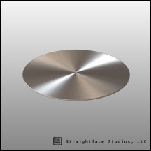 If you were to take the cross section of a brushed metal object you would find a series of small grooves etched into the object. You could attempt to simulate this using a very fine/high resolution bump map however the sampling rate required to eliminate aliasing would probably be prohibitive come render time.
In this shader we're going to use a blend material and surface normals to create a similar effect but much more rapidly than a brute force approach.
Instead of a series of small grooves we'll just have one material which simulates one side of a pyramid and a second for the opposite side. When blended together it'll give the impression that it's reflecting both directions simultaneously. By reducing the glossiness of the reflection we can also give the illusion of smoothing the grooves slightly.
In Practice:
Enough theory here is how to do it in Brazil. First let's start with 'one side' and then we'll instance all of our settings to the second material which will render the opposite angle.
1) Create a new Brazil2 Chrome material. We'll call it "Radial_Reflect_A".
2) In the Bump map slot we'll add a Gradient Ramp map. Go ahead and give it a name such as "Radial_Grad".
3) Under Gradient Type in the properties rollout select Radial. This will create the angled normal for one side of the pyramid.

[This step could also be replaced with a texture if you wanted to create overlapping brushed metal spots. The only important thing is to have a radial gradient of some sort.]
4) Back up at the B2 Chrome level: Enable Glossiness and choose "Phong" from the type rollout.
5) In the Focus map create an RGB Multiply map.
Give it a name such as "Refl_Gloss"
Set Color#1 to about 128 gray.
This will later let us instance the glossiness setting between the two materials.
6) Back up at the B2 Chrome level: Instance the Refl_Gloss map into the Specular Glossiness.
7) Create another RGB Multiply Map ("Spec_Level") in the Specular Level Map slot and set color #1 to white.
8) Create another RGB Multiply Map ("Refl_color") in the Specular Col. Channel.
9) Instance Refl_color into the reflection Filter map slot.
The first copy of the material is done. Next it'll just be a matter of creating its doppelganger.
10) Click the material type slot next to the materials name (Brazil2 Chrome) and choose Blend. When prompted be sure to choose "Keep old material as sub-material".

11) Set the Blend's Mix Amount to 50.0
12) Copy Radial_Reflect_A into slot #2 and rename it to something like "Radial_Reflect_B"
13) Go into your Radial Reflect B and change the Bump amount from 30 to -30.
14) The only thing left to do is Copy and Paste (instance) each map from Reflect A into the corresponding map slots in Reflect B. (Right click "Copy" on source. Right click "Paste (Instanced)" on destination map)
You can now adjust any of those maps and have them carry over to the opposite material automatically.


